Development of the shape for Magic Scooter 1
|
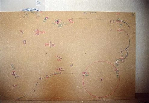
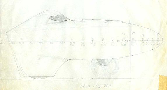
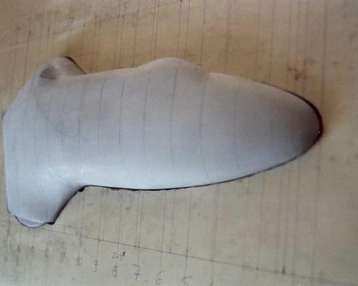
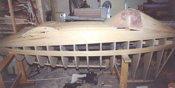
MS1 was planned from the start as a fully faired bike, i.e. the form of the fairing was not fitted to an existing unfaired bike, but bike and fairing were planned and fitted to each other at the same time. For this I checked out the optimal seat position, especially with regard to the best possible ergonomy and compatibility to the position on racebike and mountainbike with the smallest possible frontal area and sufficient view at the same time. To be able to lay the bottom bracket as high as possible for max. power development and still be able to look forward, I quickly had fixed the concept head lid with small visor in combination with hills for the toes . A big glass cockpit ( from the front to behind the head ) was out of the question in principle because of the resulting bad climate inside, worse transparency and higher costs. To get data as exact as possible about the necessary size of the fairing I fixed a big chip board vertically on the wall and placed the unfaired bike ( in the first stage still a steel prototype ) on a hometrainer next to it. So I could take ( partly with the help of a second person ) the exact widths and fix them by angle iron on the chip board.  After countless and optically less promising sketches for the main contours I made use of standardized NACA-profiles in the end to achieve harmonical courses [ "Theory of Wing Sections" by Abbott / Doenhoff, Dover Books, ISBN 0-486-60586-8 ]. In the top view I decided for the laminar profile NACA 16-015 . Because of the biggest required widths being at the shoulders and elbows and therefore in the back half of the bike, the use of a laminar profile was obligatory. The profile got adapted to the size of MS1, that is length 270cm and width 46cm , i.e. 17% thickness/length ( instead of 15% ).  The profile for the side view should be a little flattened because of the nearness of the bottom. And the max. thickness should also be reached at about 50% length. As the profile gets "disfigured" anyway by the head lid and the integrated fairing for the back wheel I was able to trick a bit in choosing the profile. In the end my choice was the profile NACA 64(4)-221, which reachs its max. thickness at about 37% (upper surface) resp. 35% (lower surface). But I´ve used only 78% of the profile length to the total fairing length. Therefore the max. thicknesses of the profiles lie with 45-47% ( side view ) resp. 50% ( top view ) not too wide apart.  With the help of the fixed measurements on the board and the chosen profiles I tried then to design the cross-sections to be as attractive as possible and with it to integrate the head lid and the rear wheel fairing in a harmonious way. To get a better impression I manufactured a model in tenth scale and then worked on it in detail as long as the result was acceptable to me.  From this model I took stencils with the cross-sections in definite distances, transfered them to graph paper and then to chip boards M 1:1 .  I fixed the boards on to two firm square steel bars and fixed them at the same distances. Thin wooden strips got stuck then onto the edges of the boards and the surfaces got sanded and filled, covered with glass fiber and finished. |